
Why Touchless Faucets Misbehave
A field guide to false activation, missed detection, run-on, weak flow and inconsistent performance—built for architects, plumbing engineers, contractors and facility teams.
A sensor faucet is not only a faucet. It is a small control system operating beside reflective surfaces, moving hands, changing light, variable pressure and a basin that can either support or confuse detection.
When performance is poor, replacing the faucet is often the wrong first response. The symptom may come from range settings, an incompatible basin, unstable power, debris, a pinched cable, a blocked filter, an incorrect mixing arrangement or a commissioning step that was never completed.
This report complements the site’s technical faucet research hub and its overview of sensor versus digital faucet controls.
What the faucet is telling you
False activation
The faucet starts without a deliberate hand target. Investigate reflections, sensor range, nearby movement, basin geometry and unintended objects inside the detection zone.
Missed detection
Hands enter the expected area but water does not start. Check power, connectors, target position, sensor obstruction, calibration and shutoffs before replacing parts.
Run-on or continuous flow
Separate a programmed shutoff delay from an actual fault. Then examine sensor lock-on, debris, solenoid condition, pressure and manual-override position.
Weak or erratic flow
Look beyond the electronics. Closed stops, clogged filters, aerator deposits, pressure changes and supply debris commonly alter delivery.
Too hot or too cold
Review the mixing device, hot and cold supplies, check valves, temperature-limiting strategy and whether the selected faucet includes local adjustment.
Works only sometimes
Intermittency often points to marginal power, loose connections, inconsistent target presentation or a condition that changes with lighting, cleaning or occupancy.
Troubleshoot from the room inward
Begin with visible, reversible checks before disturbing valves or electronics. Always follow the exact manufacturer’s installation and service instructions.
| Observed condition | Possible contributors | Safe first checks | Escalate when |
|---|---|---|---|
| Activates by itself | Range too long, reflective bowl, nearby object, soap dispenser interaction, unstable calibration | Clear the basin and deck; observe the trigger; compare range with the manual | Activation continues after correct setup and controlled testing |
| Does not activate | Power interruption, closed stop, disconnected cable, blocked sensor, target outside zone | Verify supply, power indication, clean sensor surface and test the documented hand position | Wiring, transformer or internal component diagnosis is required |
| Stays on | Sensor lock-on, debris at solenoid, manual override, damaged diaphragm or valve component | Remove targets, cycle as directed, inspect accessible filters and confirm override position | Water cannot be stopped normally or valve service is required |
| Low flow | Partially closed stop, clogged inlet filter, aerator restriction, low pressure, kinked supply | Compare adjacent fixtures, inspect accessible screens and confirm stops | Building pressure or concealed supply conditions need investigation |
| Short battery life | High traffic, repeated false activations, poor battery quality, wiring fault, unsuitable settings | Review event frequency, activation history and specified battery type | Consumption remains abnormal after settings and batteries are verified |
| Splashing | Wrong outlet, excessive flow, stream strikes drain or bowl wall, shallow basin | Observe landing point and compare faucet, outlet and basin drawings | Flow control or fixture geometry must be changed |
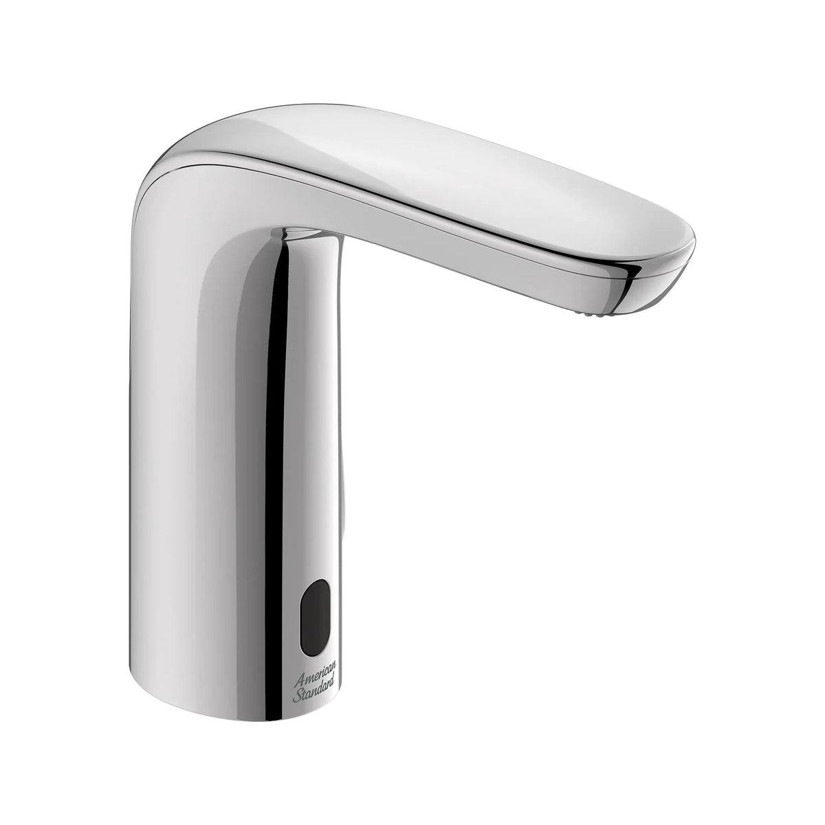
Access determines whether troubleshooting is practical
A commissioning plan should identify where the sensor, controller, power source, solenoid, filters, mixing device and shutoffs are located. A fixture may look simple above the counter while depending on crowded or inaccessible components below.
- Keep cables identifiable and protected from sharp edges.
- Leave enough room to disconnect serviceable parts.
- Do not bury transformers or valves behind permanent finishes.
- Record the installed configuration, not only the product family.

Wall mounting raises the cost of missing information
When controls or valves are concealed, access must be part of the design. The commissioning record should show the access-panel location, concealed component arrangement, power route and mixing strategy.
Wall-mounted faucet and soap-dispenser pairs also need independent testing. A visual match does not guarantee that their detection zones or service requirements are compatible.
The basin is part of the sensing system
Highly reflective bowls, dark surfaces, steep rear walls, drains, overflow openings and nearby accessories can change how an electronic faucet behaves. The correct response is model-specific commissioning with the actual basin—not a universal range setting.
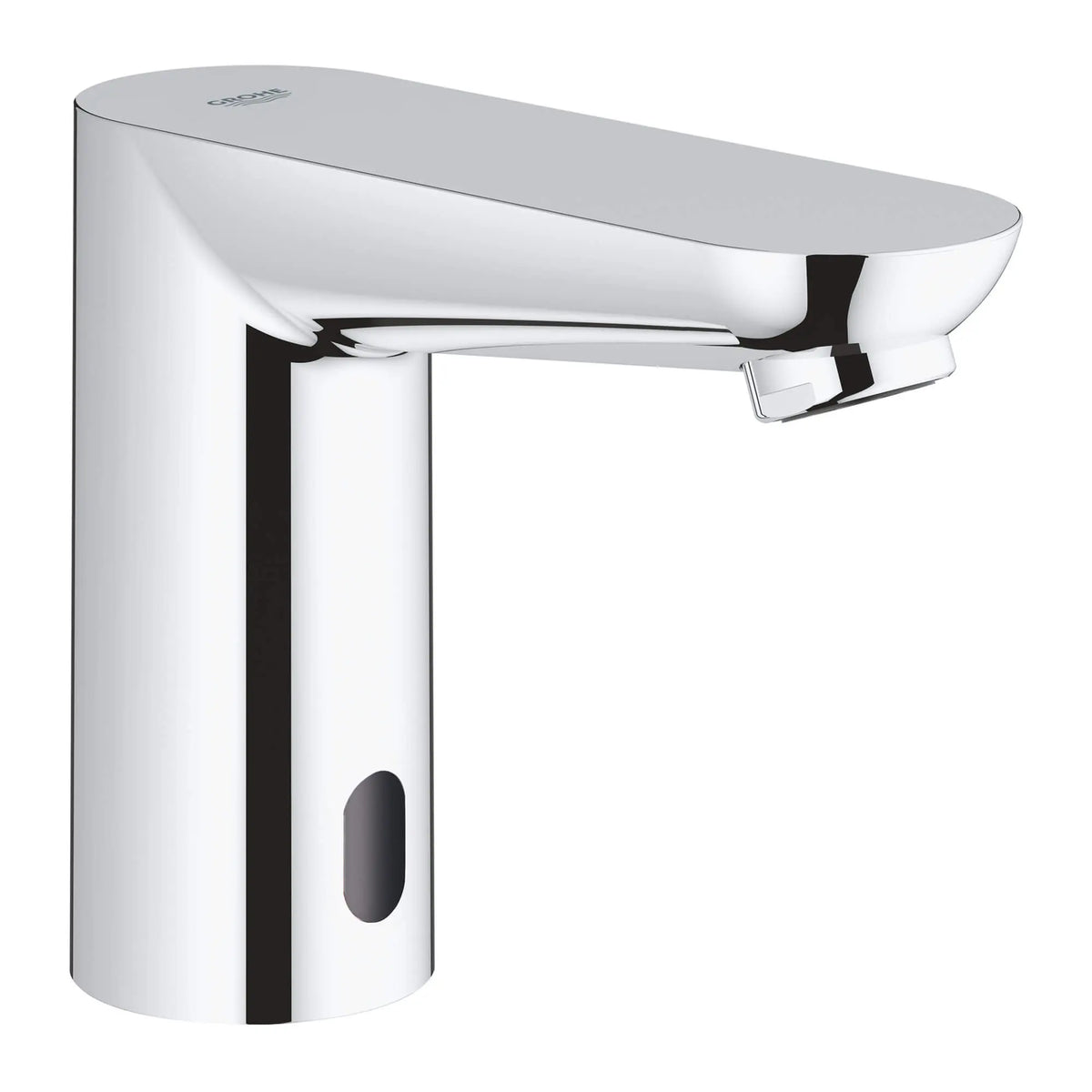
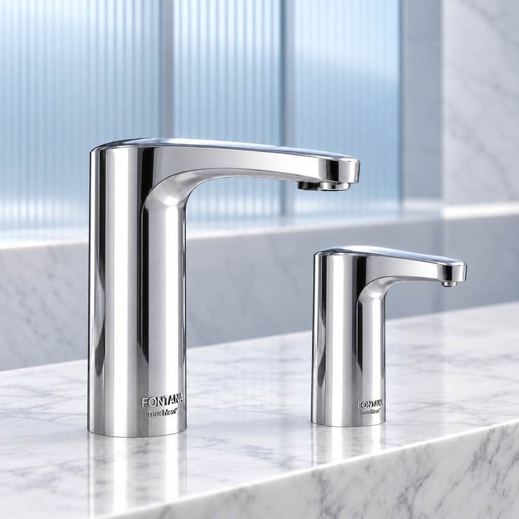
Compact sensor geometry
A short, compact body changes the relationship between sensor position, user hands and basin. Commission the exact faucet-and-basin pairing.
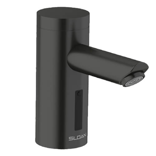
Commercial configuration discipline
Product families can contain multiple flow, power and mixing variants. Troubleshooting starts by identifying the complete installed model.
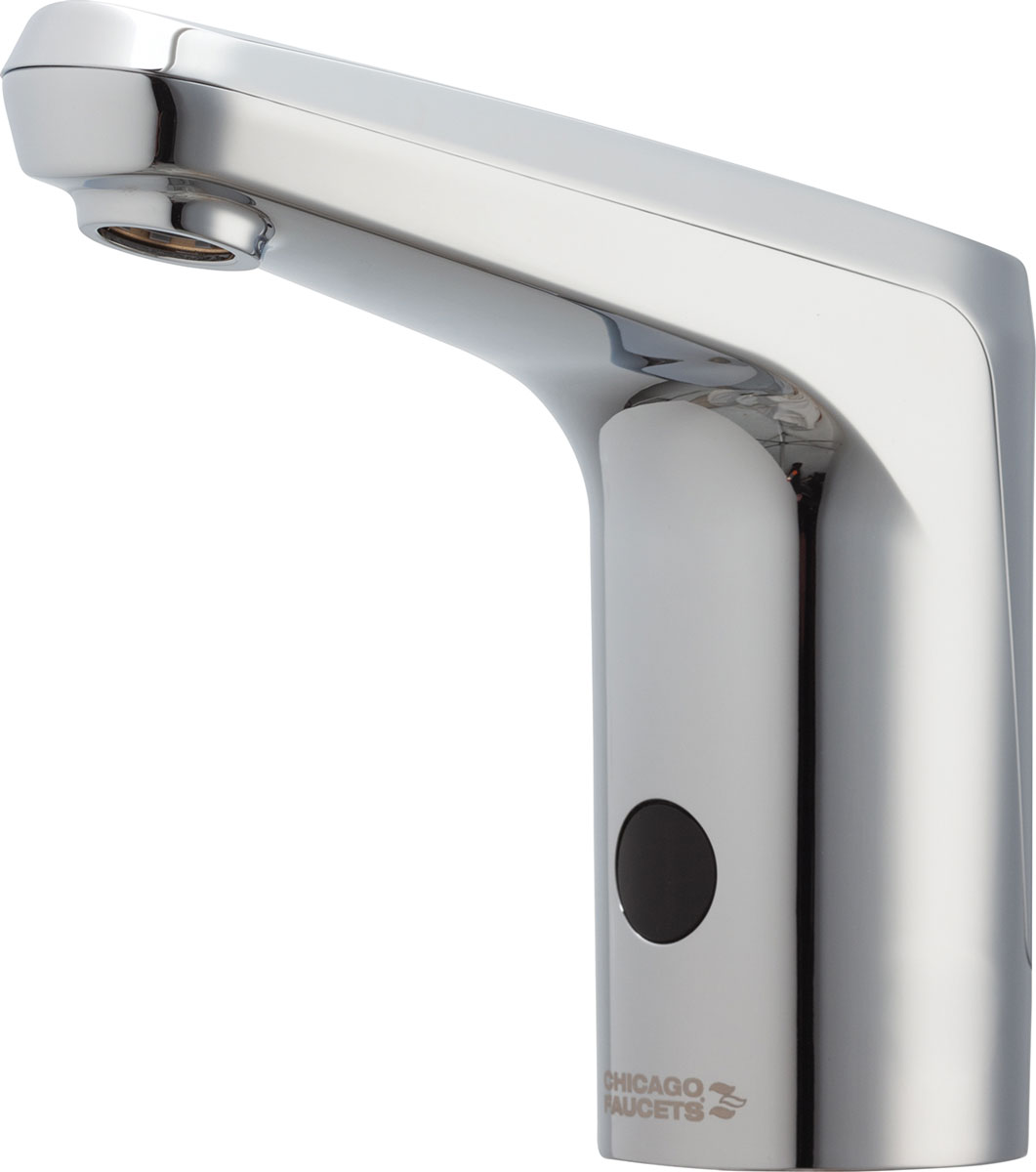
Adjustability needs governance
When settings can be configured, record the approved commissioning values. Otherwise later service teams cannot distinguish design intent from field changes.

Options must match the record
A modular family may support several project needs, but maintenance depends on knowing which power, outlet and control configuration was installed.
Faucet and soap sensors can create separate problems
A coordinated appearance should not obscure the fact that two independent electronic devices are operating in close proximity. Test soap delivery and water activation in sequence, using realistic hand movements.

Test the complete user journey
Observe soap request, hand transfer, water activation and shutoff. The user should not need to search for either detection zone.
Alignment does not equal calibration
Even a visually symmetrical pair needs separate range, dose, flow and timeout verification. Mark final settings in the closeout record.
Different forms create different diagnostic access

Familiar form, electronic system
A conventional silhouette can conceal electronic dependencies. Commissioning should cover the system, not only water delivery.

Purpose-built washroom hardware
Commercial form can improve visual legibility, but basin compatibility and accessible filters still need field verification.
A defensible commissioning sequence
The exact procedure must follow the manufacturer’s instructions. The structure below helps project teams organize observations and ownership without substituting for product-specific requirements.
Do and don’t
Do
- Use the exact installation and service manual for the installed model.
- Shut off water and power when the documented procedure requires it.
- Test with the final basin, lighting and accessories in place.
- Record settings and symptoms before changing anything.
- Escalate electrical, valve and concealed-work issues to qualified personnel.
Don’t
- Assume every no-flow symptom is a failed sensor.
- Increase range repeatedly without observing unintended targets.
- Swap components between models without manufacturer authorization.
- Bypass temperature protection or safety devices.
- Close the project without a fixture-by-fixture commissioning record.
Make correct operation a closeout deliverable
Require documented activation, shutoff, flow, temperature, splash and service-access checks for each representative fixture type. Train the owner on normal indications, approved adjustments and escalation paths. A touchless faucet that is merely powered on is not necessarily commissioned.
Research references
- U.S. EPA WaterSense — Bathroom Faucets
- BestBathroomFaucets.com — research method
- Current manufacturer product and technical pages linked throughout this article.